
Arduino NANO
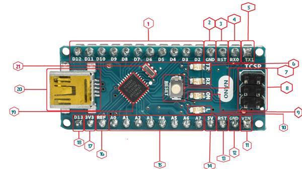
- Digital I/O (1, 4, 5, 18)
- Arduino contain 13 GPIO pins which can be used to reading digital data and writing digital data.
- Pin 0 and 1 are RX and TX pin by default which is used for receiving and transmission of data respectively. They can also be use well as GPIO pin.
- Pin numbers (3, 5, 6, 10 and 11) are PWM enabled pin which can be used as receiving digital input and giving analog output.
- GND: Provide ground to your circuit.
- Reset PIN:
Reset pin is same as reset button you can set it high to start program in Arduino from initial level or from start.
4, 5. TX and RX PINs:
Used for serial data transection. Pin 0 and 1 are RX and TX pin by default which is used for receiving and transmission of data respectively. They can also be use well as GPIO pin.
- TX and RX LEDs:
RX and TX pins stand for Receiving and Transmitting pins of Arduino used for Serial communication. TX and RX LED are connected to pin no 0 and 1 thus whenever the Arduino send or receive data over serial pins, the LED connected to TX and RX blinks respectively. 0 and 1 are the default RX and TX pin of Arduino although you can make your own RX and TX by using “SoftwareSerial” library.
- Reset Button:
Reset button is a hardware button on Arduino UNO board. On pressing reset button it stops whatever the software might be doing and start the code from an initial level.
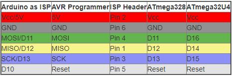
- ICSP Header:
If you look carefully in the image below, you would find that these pins corresponds to MISO, MOSI, SCK, Reset, VCC, GND
- MISO (Master In Slave Out) - The Slave line for sending data to the master,
- MOSI (Master Out Slave In) - The Master line for sending data to the peripherals,
- SCK (Serial Clock) - The clock pulses which synchronize data transmission generated by the master
Provide an alternative for programming the board other than USB.
- Power Led:
The power led is an indicator which ensure that the board is in “ON” state.
- Inbuilt Led:
Arduino NANO is built for beginners and Arduino ensures that one can get started without an external input or output. For this Arduino provide an inbuilt LED in case you don’t have any or you don’t want to attach one. The inbuilt LED work on PIN No. 13 of Arduino board you can set PIN No. 13 to HIGH or LOW to make the led ON and OFF.
11. Vin:
The input voltage to the Arduino board when it's using an external power source (as opposed to 5 volts from the USB connection or other regulated power source). You can supply voltage through this pin via battery.
- GND:
Provide ground to your circuit.
- Reset PIN:
Reset pin is same as reset button you can set it high to start program in Arduino from initial level or from start.
- 5v:
Provide a 5 output volt.
- Analog Pins:
The Arduino NANO has 8 pins from A0 to A7 for receiving analog input like temp, humidity and converting it into digital data for microcontroller. Analog pins can also be used as digital GPIO pins. Notice how Pin A0-A7 are labelled Analog IN. This is primarily because these pins are used as input pins. They take inputs in the form of Analog signals, and return values between 0 and 1023 (that’s because the Arduino NANO has a 10 bit Analog to Digital converter, or 210210 resolution).
- AREF PIN:
AREF refer to analog reference which is used to set an external voltage reference for upper limit of an analog input pins. By default it is 5v.
17. 3v:
Provide a 3.3 output volt.
18. D13:
Just another digital GPIO pin.
- Main Microcontroller:
Microcontroller is the brain of the board each Arduino has its own microcontroller. The microcontrollers are usually of Atmel Company. It performs all the I/O operation needed for the board.
- Power USB:
Arduino board can be powered by using the USB cable from your computer. All you need to do is connect the USB cable to the USB connection.
- SMD CRYSTAL:
SMD crystal is used for time management.